SCHENCK 511RBTU – BALANCING MACHINE FOR E-MOBILITY MOTOR
1. 511RBTU Overview and Application
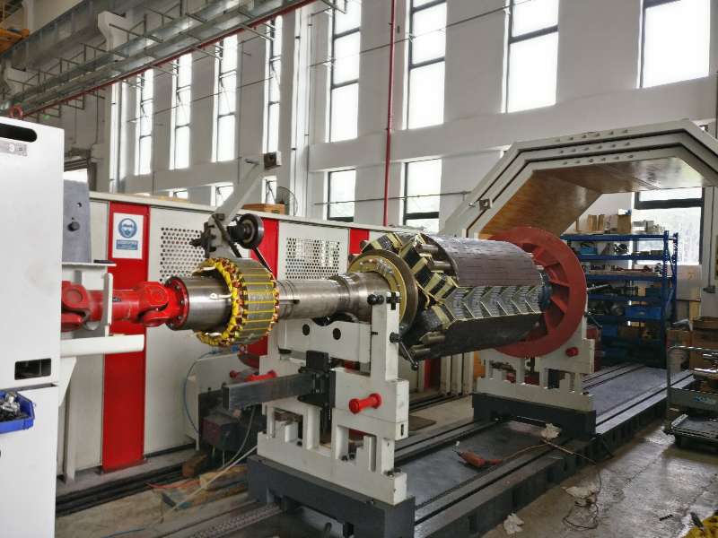
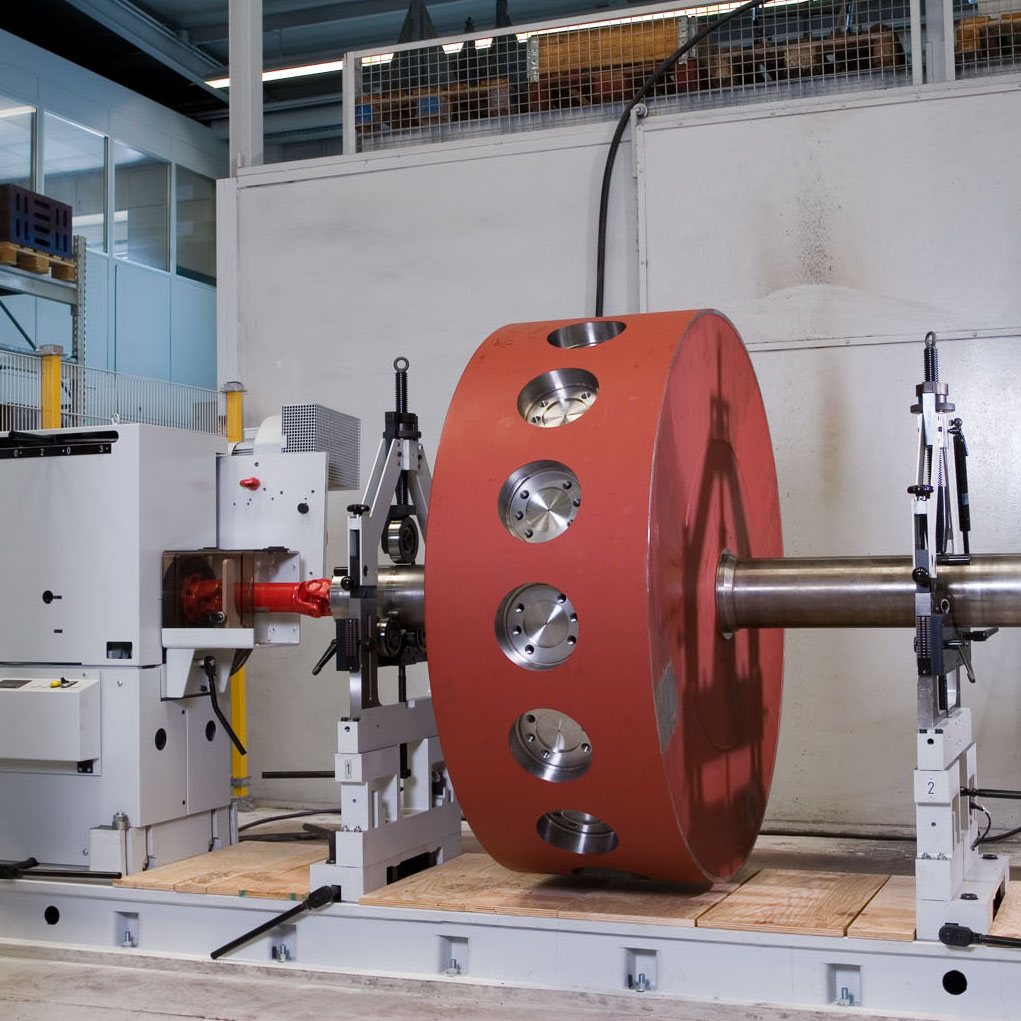
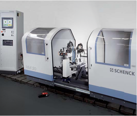
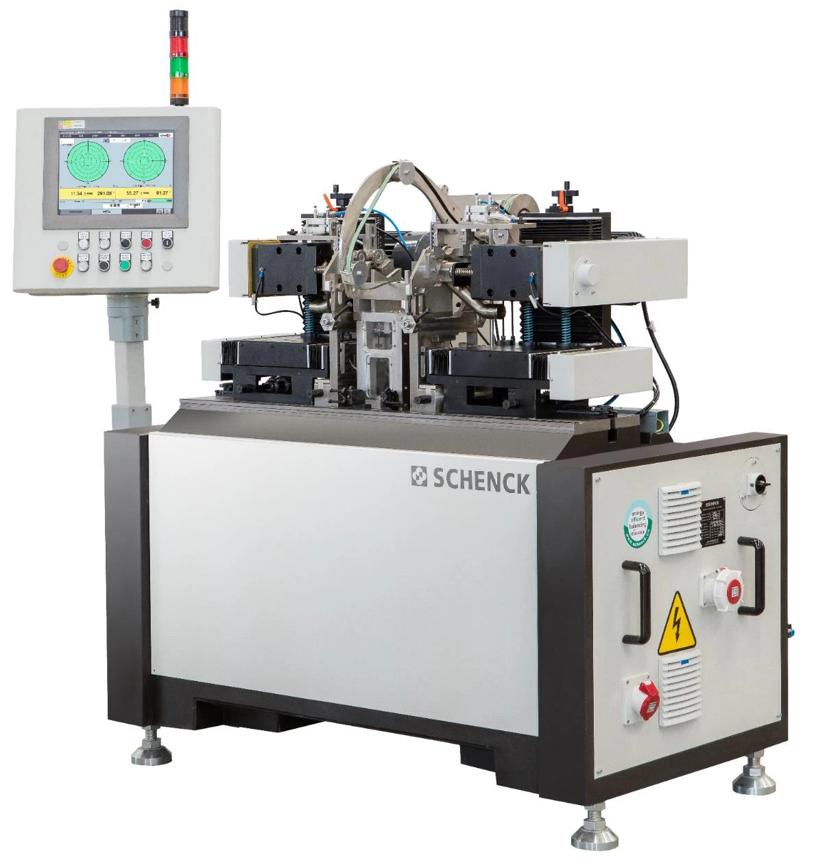
The SCHENCK 511RBTU balancing machine is designed specifically for e-mobility motors. The machine combines balancing and correction processes in an integrated system, providing high accuracy, reliability and efficient operation.
Key Features
- Integrated measuring and correction stations on a mineral casting machine bed.
- Reliable and accurate SCHENCK belt drive system.
- Automatic indexing and correction after balancing.
- Axial drilling with chip suction unit.
- SCHENCK CAB870 measuring unit for stable and accurate balancing results.
- Short cycle time.
- Compact footprint.
- Easy and user-friendly operation.
- Quick and easy changeover between different rotor types.
- Automatic storage of unbalance data.
- High reliability and operational stability.
- Automatic loading and unloading available as an option.
- MES integration and barcode scanning available as options.
2. Machine Function and Structure
2.1 Functions Overview
The machine is equipped with a manual emergency stop button. When the emergency stop button is pressed, the machine stops immediately. After the reset button is pressed, all movable components return to their initial positions.
The control cabinet is cooled by fans, while all proximity switches are equipped with indicator lamps for easy status monitoring. A three-color signal lamp indicates the current operating status of the machine.
The machine is operated and monitored through a touch-screen HMI, providing an intuitive and user-friendly interface. A standard equipment nameplate indicates the machine name, type, delivery date and other important technical parameters.
All machine components, including welded parts, are processed by chamfering and polishing to ensure safe and high-quality finishing.
Additional functions and specifications include:
- Operating noise level: ≤75 dB(A).
- Built-in diagnostic function for identifying, recording and displaying machine errors and malfunctions.
- Touch-screen HMI.
- 10% spare PLC input/output points reserved for future interface expansion.
2.2 Machine Structure
Measuring Unit
The measuring unit includes:
- Complete pedestal with roller bearings.
- Belt drive with AC servo motor.
- Electrodynamic vibration pickups and angular reference pickups.
- Adjustable rotating thrust stops for quick changeover between rotor types.
Correction Unit
The correction unit includes:
- Drilling unit driven by AC motor.
- Horizontal moving unit driven by servo motor.
- Belt positioning device.
- Lifting device for the rotor during drilling.
- Pneumatic clamping device for securing the rotor.
- Chip suction unit.
Control System
Main components of the control system include:
- Main pneumatic components: FESTO.
- Touch screen & IPC: Advantech.
- PLC: Mitsubishi.
- Measuring unit: SCHENCK CAB870.
- Main electrical components: Siemens, Schneider and OMRON.
- Optoelectronic sensors: SCHENCK.
- Vibration pickups: SCHENCK.
2.3 Machine Layout
Machine layout is provided in the attached technical drawings.
3. Basic Machine Data and Rotor Specifications
3.1 Machine Data
| Parameter | Specification |
|---|---|
| Machine weight | Approximately 1,600 kg |
| Electrical power consumption | Approximately 13 kVA |
| Power supply | 380 V, 50 Hz, 3-phase |
| Control voltage | DC 24 V |
| Air consumption | Approximately 10 Nm³/h |
| Air pressure | ≥6.0 bar |
| Machine color | RAL7021 / RAL703* |
| Minimum achievable residual unbalance | 0.1 gmm/kg, but not less than 2 gmm |
3.2 Rotor Specifications
| Parameter | Specification |
|---|---|
| Rotor weight | 8–50 kg |
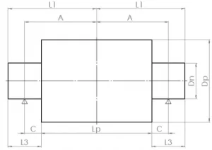
| Shaft length L1 | 65–200 mm |
| Distance from shaft end to drilling plate L3 | 10–130 mm |
| Shaft diameter Dn | 30–70 mm |
| Support position A | 82–185 mm |
| Distance between support position and drilling surface C | 5–60 mm |
| Stack height Lp | 100–300 mm |
| Stack diameter Dp | 100–280 mm |
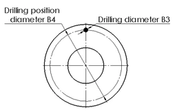
| Drilling position diameter B4 | 134–225 mm |
| Dimension requirement | B4 > 1.35Dn + 93 |
Rotor Requirements
The customer’s rotor must meet the following conditions:
- Actual rotor dimensions and tolerances must comply with the approved rotor drawing.
- Shaft runout at the bearing position should be not less than 8 μm.
- If the rotors are supplied with bearings, the tolerance between the shaft and bearing must achieve at least P6.
- Perpendicularity of the end plane against the shaft should be at least 0.1 mm.
- Shaft surface must be smooth and free of key slots.
- Armature stack must be rigid.
- Windings must remain stable without movement during rotation.
- Material to be removed during drilling must be homogeneous.
- Installation location must be free from excessive external vibration.
- Drilling positions must be free from interference with the drilling device and vacuum system.
- Drilling material must not be adsorbed onto the rotor.
3.3 Cycle Time and Changeover Time
- Average cycle time: maximum 100 seconds, with up to 4 holes on each end plate.
- Changeover time: less than 20 minutes.
4. Process Flow
Step 1 – Loading and Measurement
The operator places the workpiece into the balancing machine using a robot or gantry system and presses the start button. The protective door closes automatically, and the workpiece is measured automatically.
Step 2 – Automatic Positioning and Drilling
After measurement, the rotor is automatically indexed to the drilling position. The drilling unit removes the required amount of material automatically, while the chips generated during drilling are collected by the vacuum system.
Step 3 – Re-Check
After drilling, the rotor is automatically re-checked to verify the balancing result.
Step 4 – Unloading
If the rotor meets the specified tolerance requirements, the protective door opens automatically and the operator can remove the finished workpiece.
5. Scope of Supply
5.1 Integrated Balancing and Drilling Unit
The standard machine supply includes:
- 1 integrated balancing and drilling unit.
- 1 horizontal machine bed.
- 1 SCHENCK balancing unit.
- 1 belt drive with AC servo motor.
- 1 SCHENCK SF16 high-sensitivity vibration pickup.
- 1 SCHENCK reference pickup.
- 2 drilling units with AC servo motors.
5.2 SCHENCK CAB870 Measuring Unit
The machine is equipped with 1 SCHENCK CAB870 measuring unit, an advanced measuring system from SCHENCK RoTec, Germany.
Key features include:
- Touch-screen interface with guided operation.
- Easy communication between the computer and operator.
- Modular design.
- Networking capability.
- USB interface.
- Industrial PC with mouse and keyboard.
5.3 Control and Drive System
The control and drive system includes:
- 1 AC servo control system.
- 1 Mitsubishi PLC control system.
- 1 three-color signal lamp.
- 1 air conditioner.
- 1 pneumatic control system.
5.4 Industrial Vacuum Cleaner
- 1 industrial vacuum cleaner for chip extraction during the drilling process.
5.5 Technical Documentation
The standard technical documentation includes:
- 2 paper documents in English.
- 1 electronic document supplied on CD.
Documentation includes:
- Machine operation and maintenance manual.
- CAB870 measuring unit manual.
- Electrical diagrams.
- PLC manual.
- Assembly drawings of measuring tooling.
- Inspection report and certificate.
5.6 Tooling
- 1 complete tooling set for one rotor type.
6. Plant Requirements, Installation and Commissioning
The machine should preferably be installed on the first floor of the workshop. Installation on the second floor is also possible provided that the floor structure is sufficiently solid and the location is isolated from strong vibration sources, such as large machining equipment or punching machines.
After the machine arrives, the Buyer shall install the machine according to the technical documents supplied by the Seller and prepare the required electrical power, cables and pipelines. The Buyer shall then inform the Seller that the equipment is ready for commissioning. The Seller will be responsible for commissioning the machine at the Buyer’s workshop.
Important: The accessory box must be opened jointly by both parties and the contents must be checked against the packing list.
Services Not Included
The following items are not included in the Seller’s service scope:
- Machine foundation and machine installation.
- Power supply.
- Compressed air source.
- Electrical cables and cable ducts.
7. Acceptance
The Seller will manufacture 1 master rotor for each rotor type.
The Buyer shall provide 2 unbalanced samples for each rotor type to SCHENCK Shanghai within 2 weeks after signing the contract. These samples are required for machine design and master rotor manufacturing. The rotor dimensions must comply with the approved rotor drawings.
Before the pre-acceptance test, the Buyer shall provide 10 unbalanced samples for each rotor type to SCHENCK Shanghai.
If the required sample parts cannot be supplied on time, the machine delivery schedule will be postponed accordingly. All parts shall be delivered to the Seller’s factory under DDP terms.
The Seller will provide machine layout drawings within 2 months after contract signing for the Buyer’s review and confirmation. The Buyer shall review and confirm the drawings within 2 weeks. The machine layout drawings will include information regarding electrical power supply, compressed air supply and other relevant requirements.
7.1 Pre-Acceptance
The Seller shall inform the Buyer of the pre-acceptance date before delivery. The Buyer may delegate a maximum of 5 persons to SCHENCK Shanghai to conduct the pre-acceptance for 2 working days.
Remote pre-acceptance by video conference may be negotiated if on-site pre-acceptance is not possible.
Travel and accommodation expenses shall be borne by the Buyer.
During pre-acceptance, the Seller will provide training covering machine operation, machine setup and machine calibration.
After completion of the pre-acceptance, both the Seller and Buyer shall sign the pre-acceptance protocol.
7.2 Pre-Acceptance Criteria
The following criteria shall be applied during pre-acceptance:
- 8-hour dry cycle: The machine shall operate continuously for 8 hours without faults. Critical or serious alarms and faults are not acceptable. If an alarm or fault occurs, SCHENCK shall resolve the issue as soon as possible, and the same alarm or fault shall not occur a second time.
- The machine shall be checked according to the scope of delivery specified in Section 3.
- MU95% ≤ 10% of the part tolerance.
- Drilling performance shall comply with the approved rotor drawing.
8. Final Acceptance
Final acceptance shall take place no later than 6 months after delivery. If final acceptance is delayed due to the Buyer, the machine will be considered approved.
The Seller will assign 1 SCHENCK local agent engineer to the Buyer’s factory for a total period of 10 working days to conduct commissioning and training.
The evaluation criteria for final acceptance shall be the same as those applied during pre-acceptance.
Buyer’s Responsibilities Before Engineer Arrival
Before the Seller’s engineer arrives, the Buyer shall:
- Unload and unpack the machine components.
- Check the completeness of the delivery against the packing and shipping documents.
- Prepare the machine foundation. A standard workshop floor with 300 mm concrete depth is required.
- Move the machine to the designated installation location in the workshop.
- Prepare a sufficient number of rotors of each type for testing.
- Provide the rotors to SCHENCK Shanghai free of charge.
- Ensure that the required electrical power and compressed air supplies are available.
- Ensure that the required customer personnel are permanently available during commissioning and acceptance.
Seller’s Responsibilities During Commissioning
The Seller shall:
- Conduct final acceptance according to the same criteria applied during pre-acceptance.
- Complete the commissioning and acceptance activities.
- Provide the required technical support and training.
- After completion of the above activities, the Buyer and Seller shall sign the final acceptance protocol.
9. Personnel Training
The Seller’s engineer will provide technical training to the Buyer’s operating and technical personnel at the Buyer’s factory.
The training includes:
- Balancing principles.
- Machine operation.
- Basic machine maintenance.
Training duration: approximately 2 working days.
10. Service and Technical Support
10.1 Service Definition
During the warranty period, the Seller shall provide free machine service and replacement parts provided that the machine is operated correctly and in accordance with the operating instructions.
If failures or damage are caused by improper operation or other maloperations by the Buyer, the Seller may charge the corresponding service and replacement costs.
After the warranty period expires, the Seller shall provide lifetime technical support and service on a chargeable basis.
10.2 Service Response Time
SCHENCK commits to the following response times after receiving a machine breakdown notification:
- Remote support: If the problem can be resolved remotely, SCHENCK will respond within 2 hours.
- On-site service: If the problem cannot be resolved through remote communication, the target arrival time for the SCHENCK local agent’s service engineer is within 24 hours.
- Special cases: For special circumstances, the service engineer will arrive on site within 48 hours.